- 1 Introduction
- 2 Designs of crop protection sprayers
- 2.1 Mounted sprayers
- 2.2 Platform-mounted sprayers
- 2.3 Trailed sprayers
- 2.4 Self-propelled sprayers
- 2.5 Parameters of different sprayer designs
- 2.6 Evaluation of different sprayer designs
- 3 Design
- 3.1 Tank forms
- 3.2 Pumps
- 3.3 Agitator
- 3.4 Fluid filter
- 3.5 Steering
- 3.6 Fittings
- 3.7 Booms
- 3.8 Nozzles
- 4 Outlook
- 5 Literature
1 Introduction
Following DLG Expert Knowledge Series 409 ‘Correct crop protection – things to check before you start” [1], DLG Expert Knowledge Series 413 ‘Pflanzenschutz ohne Wasser zu gefährden’ (Crop protection without endangering water) [2] and DLG Expert Knowledge Series 452 ‘Lagerung von Pflanzenschutzmitteln auf dem landwirtschaftlichen Betrieb’ (Storage of crop protection agents on farms) [3], this Expert Knowledge Series pamphlet deals in detail with the technical options for the environmentally-friendly application of liquid crop protection agents in arable farming. Bearing the scope of the Expert Knowledge Series pamphlet in mind, only conventional crop protection sprayers are dealt with, not air blast sprayers, atomisers, wiper implements or special designs.
2 Designs of crop protection sprayers
Crop protection sprayers are designed as mounted implements for the rear three-point-linkage system, as load platform-mounted or trailed and as self-propelled working machines. The feature common to all of the different designs is that they consist of an implement frame, a tank for the spray liquid, the pump, the control fittings and the crop sprayer boom. Trailed sprayers are additionally equipped with a chassis, and self-propelled crop sprayers with a chassis, a driver’s cab, a drive and a propulsion engine.
2.1 Mounted sprayers
Crop protection sprayers mounted on the tractor’s rear power lift are available with tank sizes from 400 litres
to 2,200 litres and spraying booms from 12 to 30 metres. As the size of the tank increases, attention is paid to the fact that the tanks are slender and tall so that the implement’s centre of gravity is as close to the tractor as possible. Nevertheless, rear mounting usually requires an additional front ballast to ensure steerability. When driving as usual on public highways with a full tank, adherence to the permissible gross vehicle weight and the maximum permissible axle and wheel loads of the tractor must be ensured.
Advantages: Many manufacturers, models, sizes and items of equipment, inexpensive.
Disadvantages: Limited work rate, unfavourable load distribution.
One alternative is the combination of a rear-mounted crop protection sprayer with a front-mounted tank (volume of up to 1,500 litres), which increases the capacity and acts as an ideal counterweight when emptying is coordinated. Attention must be paid to the maximum distance of 3.5 m between the steering wheel and the front edge of the front-mounted tank; exceeding this necessitates ‘suitable operational measures’ for travelling on the road in order to compensate for the limited field of vision (e. g. an accompanying person to provide guidance in locations with limited visibility, a camera/monitor system).
Advantages: Many manufacturers, models, sizes and items of equipment, flexible combination.
Disadvantages: Mounting and dismounting time-consuming, necessitates a large tractor (permissible gross vehicle weight and permissible axle and wheel loads).
2.2 Platform-mounted sprayers
The majority of system tractors such as the Unimog or Trac tractors (previously also implement carriers) offer the option of mounting specially adapted crop protection sprayer tanks in mounting areas behind the driver’s cab The spraying boom is either mounted in the three-point linkage together with the pump and the control fittings or is connected directly to the top-mounting frame. This gives rise to a tractor/implement unit that displays characteristics similar to those of a self-propelled vehicle. The tank volumes are 1,500 – 4,000 l. Again, the maximum payload and the load-bearing capability of the axles and tyres of the carrier vehicle must be observed.
Advantages: Characteristics similar to self-propelled vehicles, high system tractor utilisation.
Disadvantages: Mounting and dismounting time-consuming, limited range of system tractors and top-mounted sprayers.
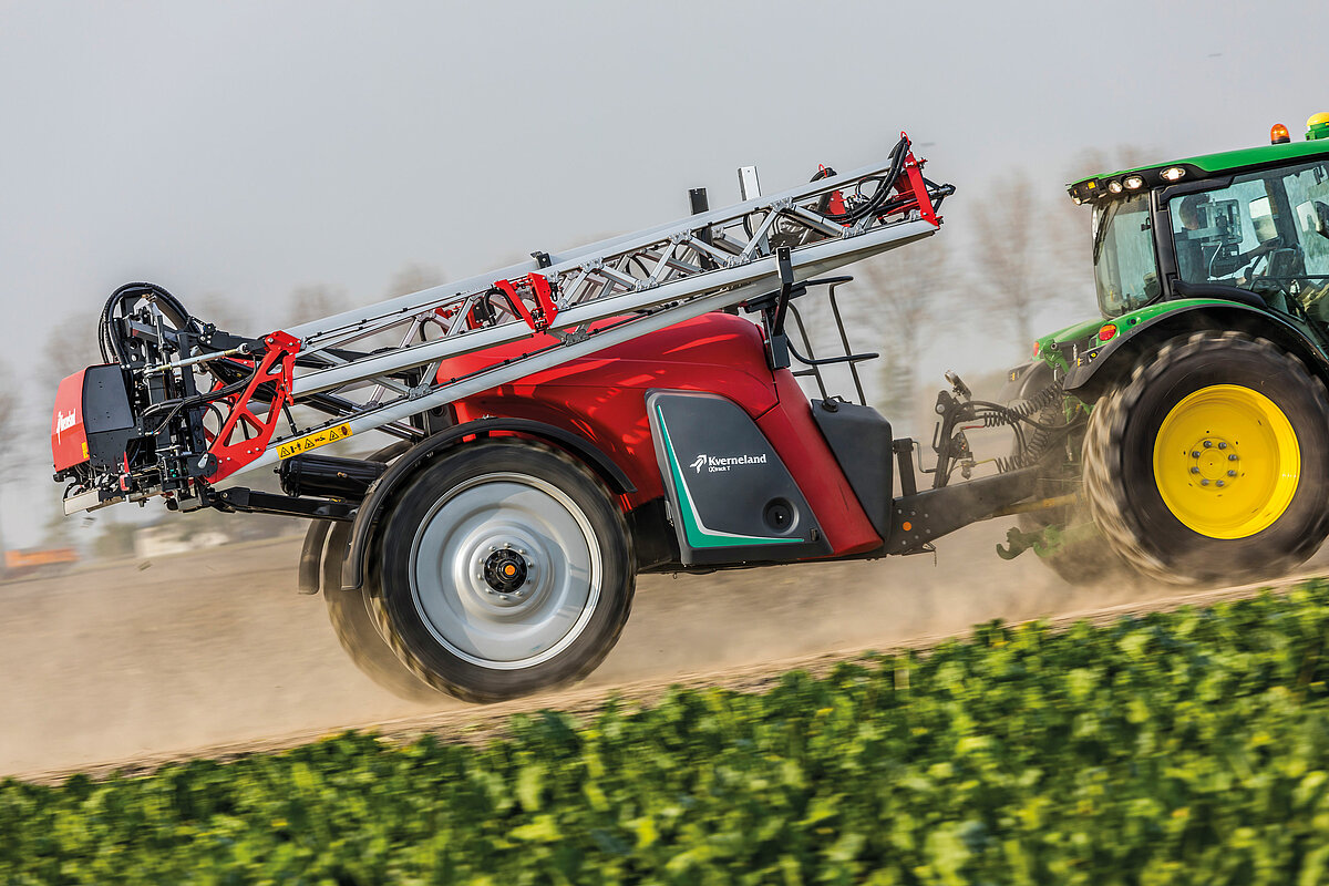
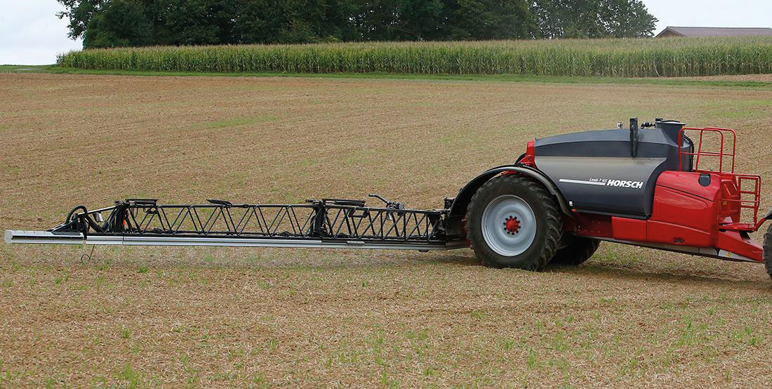
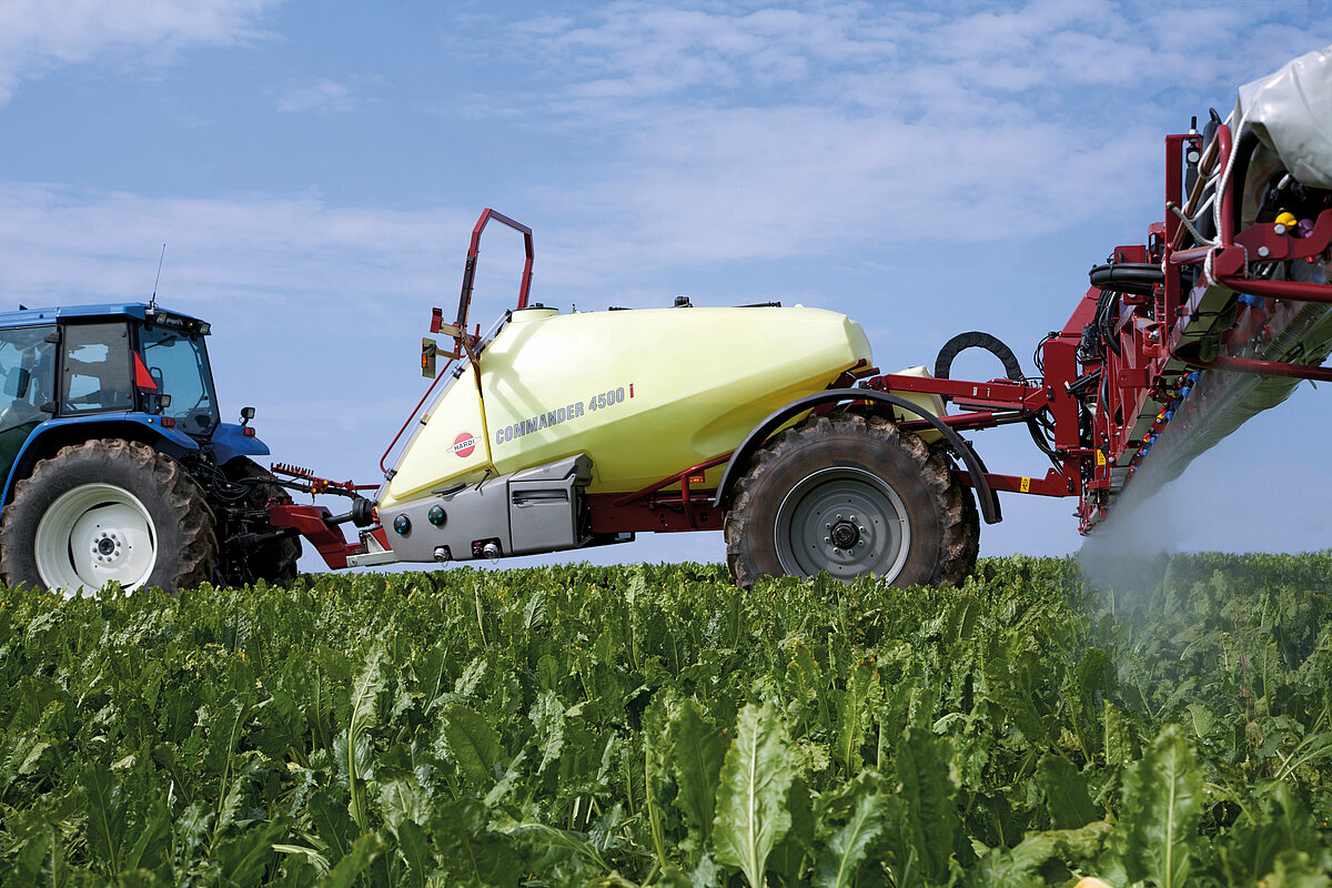
2.3 Trailed sprayers
Trailed sprayers are becoming increasingly widespread. They are designed with tank volumes of 2,000 litres to 12,000 litres, spraying booms of 12 to 50 metres and single-axle or tandem-axle chassis. To ensure that the spraying boom remains in a steady position, many of them are equipped with mechanical, pneumatic or hydropneumatic suspension. Self-steering for precise turning on the headland also forms part of the additional or basic equipment. The high gross vehicle weights and driving speeds of up to 40 km/h make it necessary to fit compressed air brakes.
Advantages: Many manufacturers, models, sizes and items of equipment, favourable load distribution, use with ‘light’ tractors possible, fast hitching and unhitching.
Disadvantages: Manoeuvrability and overview are limited, risk of tipping.
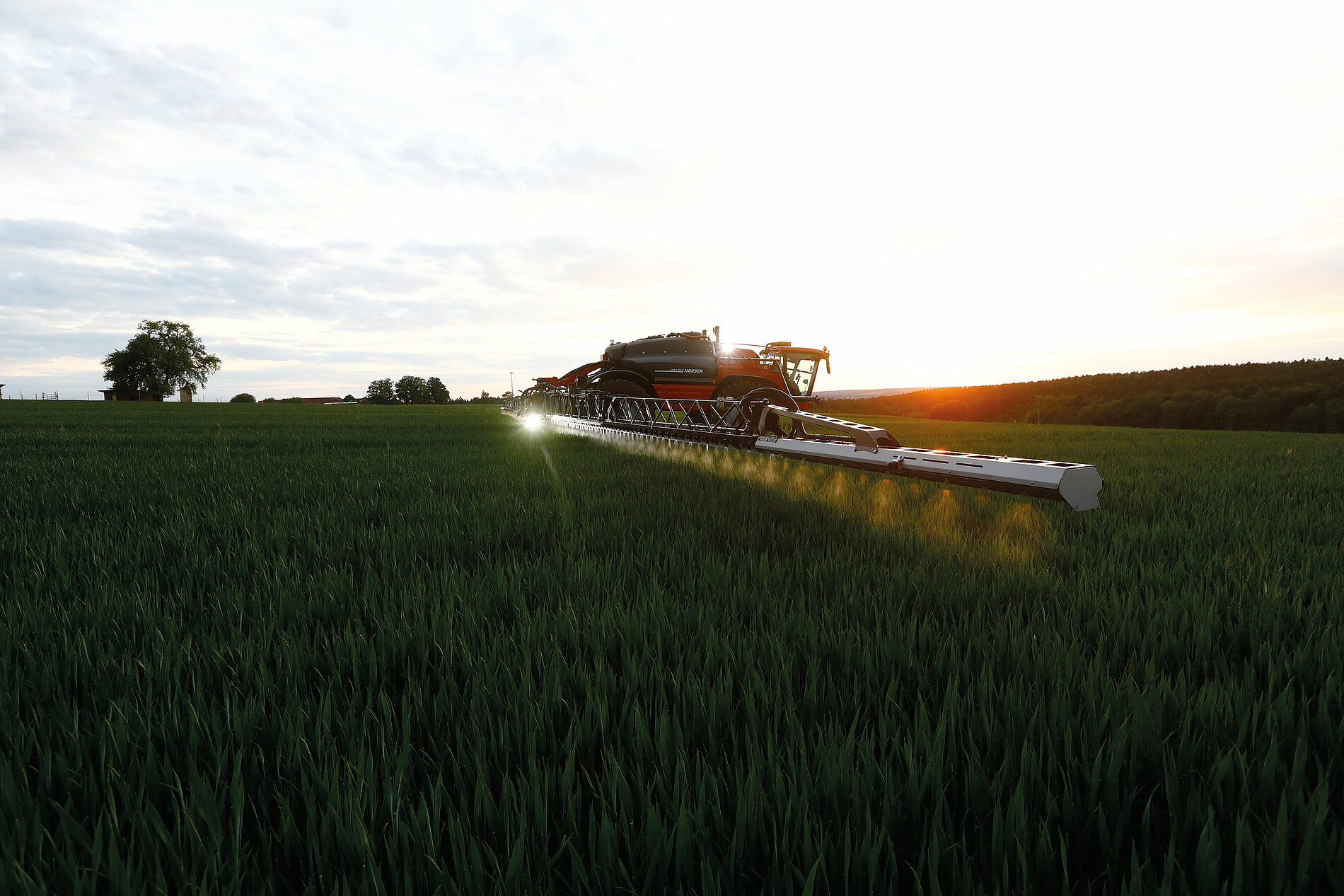
2.4 Self-propelled sprayers
Self propelled sprayers combine very high manoeuvrability with optimised operating comfort, high ground clearance (1,000 – 1,200 mm) and (usually) the option of adjusting the track width. With these characteristics, they are above all predestined for use across farms in various crops and under diverse operating conditions. Twin-axle chassis with all-wheel steering and mechanical or hydropneumatic suspension are typical. The tank volumes vary between 2,000 and 8,000 litres, and the booms between 18 and 54 metres. Initial models with a three-axle chassis enable tank volumes of over 10,000 litres. Special designs are available with particularly high ground clearances of up to 2,000 mm or with track running gear units.
Advantages: High manoeuvrability, good operating comfort, high ground clearance, high efficiency.
Disadvantages: High capital requirement.
2.5 Parameters of different sprayer designs
To facilitate classification and make selection easier, but also with regard to the evaluation carried out in section 2.6, the most important parameters for each of the typical representatives of the four sprayer designs described above are listed in the following. The compilation is oriented to the KTBL data.
Tabelle 1: Kennzahlen ausgewählter Beispiele unterschiedlicher Spritzenbauformen (KTBL MAKOST 15. 09. 2021, Selbstfahrer inkl. Diesel)
| Design | Rated volume l | Working width m | Price € | Costs with 200 l/ha | |
| Fixed €/a | Variable €/ha | ||||
| Mounted | 1,000 1,500 | 15 18 | 22,700 30,300 | 2,333 3,093 | 0.53 0.53 |
| Mounted+ front-mounted tank | 1,500 + 1,000 | 18 | 39,300 | 4,054 | 0.53 |
| Platform-mounted | 2,000 4,000 | 21 27 | 35,900 50,300 | 3,723 5,148 | 0.53 0.53 |
| Trailed | 2,500 5,000 | 24 36 | 46,100 79,100 | 4,761 8,087 | 0.55 0.55 |
| Self propelled | 4,500 6,000 | 27 36 | 296,300 336,100 | 30,256 34,360 | 7.56 8.28 |
2.6 Evaluation of different sprayer designs
The following matrix (Table 2) attempts to evaluate the representatives of the different crop protection sprayer designs characterised in Table 1 in terms of selected criteria.
Table 2: Evaluation of different sprayer designs
| Design | Efficiency | Manoeuvrability | Operating comfort | Equipment | Flexibility | Capital requirement |
| Mounted | O | ++ | O | O | + | ++ |
| Mounted + front-mounted tank | + | + | O | + | - | ++ |
| Platform-mounted | + | ++ | + | + | - | O |
| Trailed | + | O | + | ++ | ++ | O |
| Self-propelled sprayers | ++ | ++ | ++ | ++ | - | - |
Evaluation scale: ++ very good/very favourable, + good/favourable, O average, - poor/unfavourable, -- very poor/very unfavourable
Deviating evaluations can arise in individual cases depending on the individual make, machine type and machine equipment as well as the specific operating conditions. The matrix can, and is only intended to, provide indications.
3 Design
Crop protection sprayers consist of the main assemblies of the liquid tank with agitator, filling and draining device, pump with filter, pressure adjustment valves, possibly electronic measurement and control device and the spraying boom with shut-off valves, nozzle holders and nozzles. On trailed sprayers, these are joined by the chassis with suspension and steering; self-propelled crop protection sprayers are additionally equipped with a cab and an engine of different designs.
3.1 Tank forms
Irrespective of the sprayer type, crop sprayers are fitted with several tanks. The largest tank on the sprayer is used to accommodate the spray liquid. The majority of tanks are manufactured from glass fibre-reinforced plastic (GFK) or polyethylene (PE) (Figure 1). Tanks are also occasionally manufactured from stainless steel (Figure 2). The actual volume of the tank must be at least 5 % higher than the rated volume. Besides the design, factors such as the residual quantities that remain in the tank after ‘spraying empty’ are playing an increasingly important role, because the greater the residual quantity that remains in the tank, the more difficult it is to clean the implement as a whole. The interior should be designed without too many internal assemblies in order to enable effective cleaning.
The sprayer must be equipped with a fresh water tank for cleaning. The volume must be at least 10 % of the rated tank volume or ten times the dilutable residual quantity. In the latter case, the dilutable residual quantity must be specified in the operating instructions. The tank must be designed and connected to the implement so that flushing the lines with the tank filled up to the rated volume and diluting the residual quantity in the tank as well as cleaning the interior and exterior of the implement are possible.
A third tank is also mounted on the sprayer as a fresh water tank and is used for cleaning the personal protective equipment and the nozzles on the field. Its capacity is usually between 10 and 20 l.
The majority of modern crop sprayers are equipped with induction bowls with a volume of approx. 45 l; these enable comfortable filling of the sprayer with Plant Protection Products (PPP’s) (Figure 3). They are also equipped with canister flushing nozzles for immediately cleaning the PPP containers. The additional tanks and the induction bowl are made from the same material as the liquid tank. The advantages and disadvantages of the tank materials are shown in Table 3.
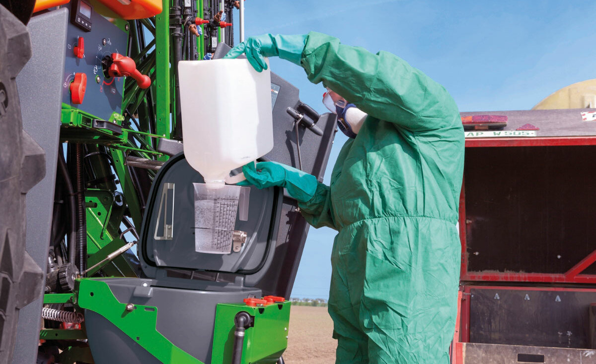
Table 3: Comparison of the various tank materials
| GFK | PE | Stainless steel | |
| Weight | O | O | O |
| Roughness (smooth inner walls) | + | + | + |
| UV stability | - | O | + |
| Mounting points | - | O | + |
| Possibility of repair | + | O | + |
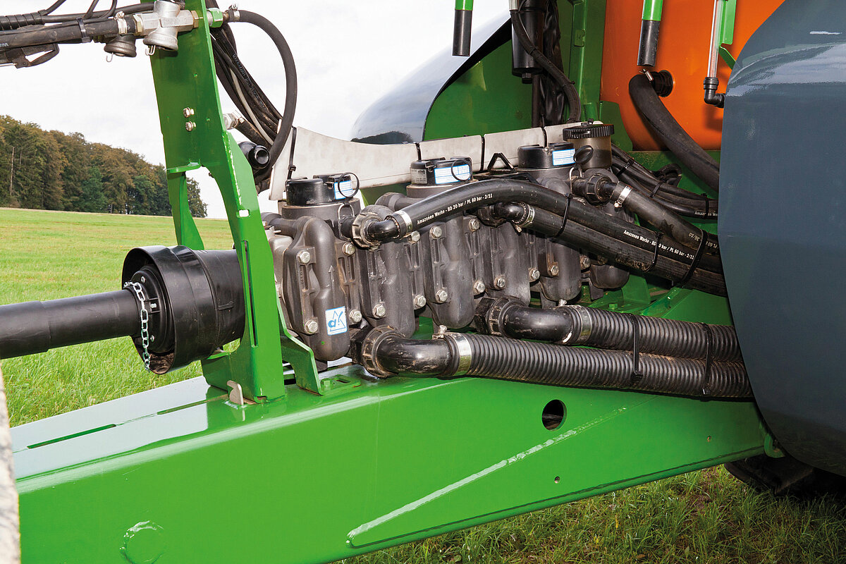
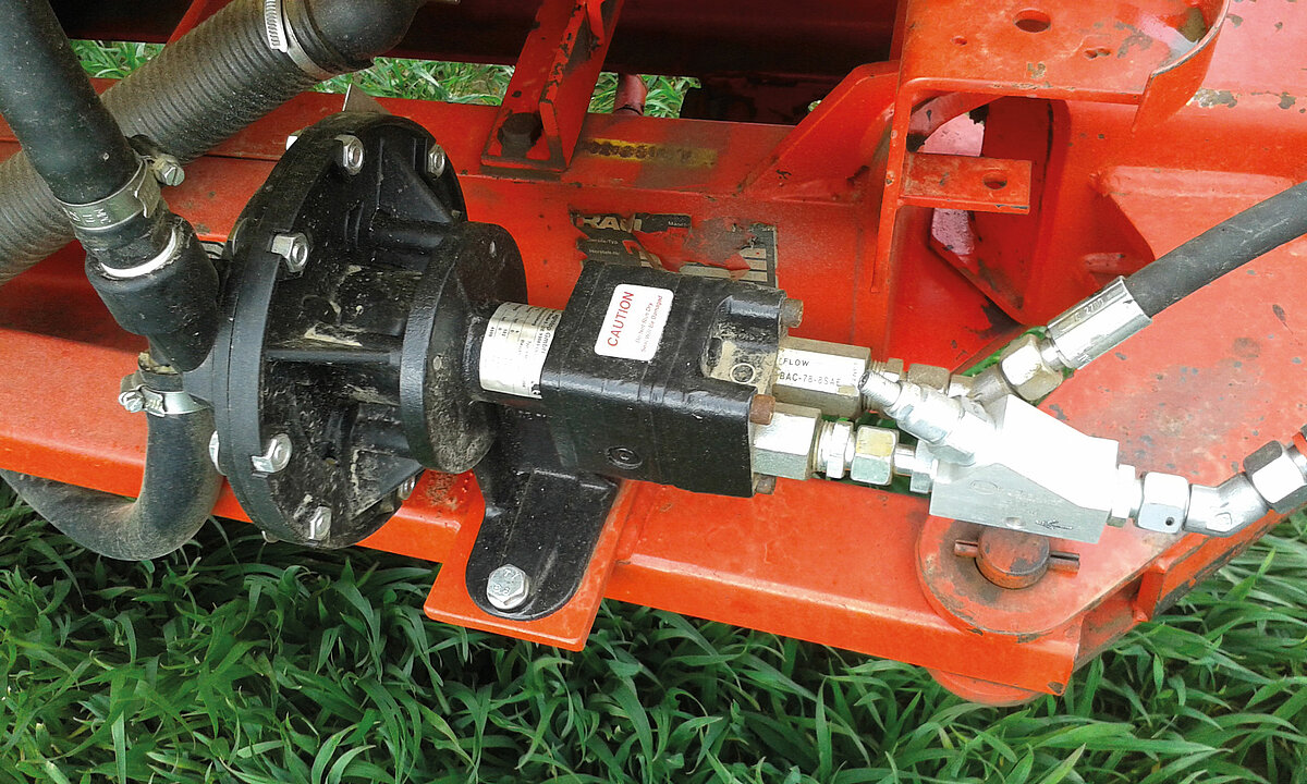
3.2 Pumps
Piston diaphragm and piston pumps are primarily used on crop sprayers. Centrifugal pumps have recently been gaining in importance, as the volumetric flow can be regulated via an oil motor, which is able to operate independently of the tractor’s engine speed.
The volumetric flow of the pump(s) must be coordinated to the implement’s liquid requirements. In addition to supplying the spraying boom (nozzles)
with spray liquid, perfect adjustment of the operating pressure and sufficient agitation performance must also be ensured.
The pump capacity for supplying the spraying boom is calculated as follows:
Volumetric flow for boom [l/min] =
working width [m] x output quantity [l/ha] x driving speed [km/h] / 60
Table 4 contains guideline values for calculating the volumetric flow required for a well-functioning agitator.
Table 4: Rule of thumb for calculating the volumetric flow required for the agitator
| Rated volume of the sprayer tank | Volumetric flow in l/min |
| Up to 1,000 l | 5 % of the rated volume |
| > 1,000 l – 2,000 l | 60 l/min |
| > 2,000 l | 3 % of the rated volume |
The agitation performance required to prevent demixing of the spray liquid must particularly be noted in the case of higher water application volumes at high driving speeds. Deviation from these guideline values is possible if injector agitators are installed. Due to the way in which they work, these are able to cope with lower volumetric flows to achieve a good agitation effect. Multiple injectors can also be installed in the tank in order to avoid dead areas. No pump capacity has to be taken into consideration for agitation with mechanical agitators.
The highest pump capacity is required during intake to fill the crop sprayer. With their high specific output with low back pressure and compact design, centrifugal pumps certainly have the edge in this regard. If piston diaphragm pumps are used, two pumps are often installed, one for spraying and one for agitation. During intake, they are activated together in the form of a twin-pump system and thereby achieve the high delivery rate that is required.
When purchasing, attention should also be paid to the position of the pump in the sprayer to enable any repairs to be undertaken with ease without having to dismantle the entire crop sprayer.
Table 5: Comparison of the various pump types
| Piston diaphragm | Piston | Centrifugal | |
| Dry running | + | O | -/O* |
| Design size | O | - | + |
| Weight | O | - | + |
| Wear | + | O | O |
| Material resistance | + | + | + |
| Delivery rate | O | - | + |
| Liquid fertiliser | + | + | + |
| Spray pressure | + | + | O |
| Self-priming | + | + | - |
Evaluation scale: + good/favourable, O average, - poor/unfavourable
* A design protected against running dry must be ensured
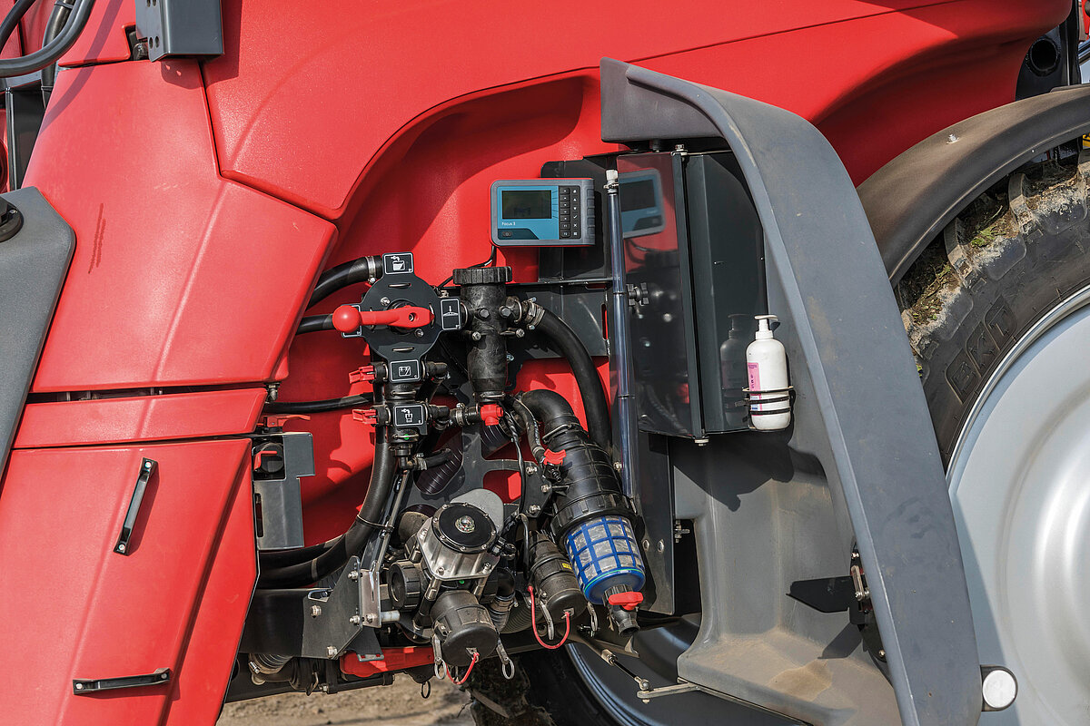
Either one of a twin-pump system’s pumps or a separate cleaning pump is used to clean the sprayer. Special cleaning programmes ensure a clean sprayer. If a separate pump (piston diaphragm or centrifugal pump) is located between the fresh water tank and the internal cleaning nozzles, this usually involves a continuous internal cleaning system. In this case, the cleaning pump’s capacity is adapted to the system, at 90 % of the nozzle output. This system is either integrated into the sprayer’s computer or is also retrofitted as a separate system on used sprayers (Figure 5). Manufacturers that have no automatic cleaning system in their product range use the separate system to comfortably clean the sprayer.
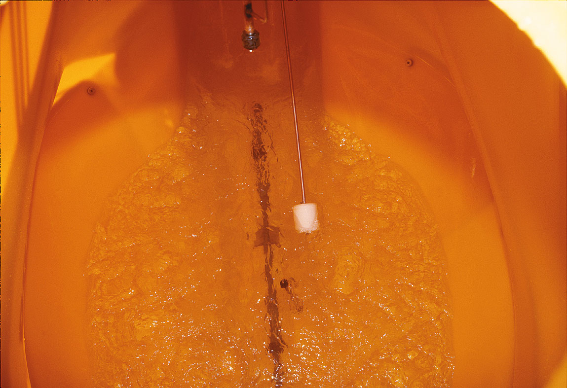
3.3 Agitator
Particular attention must be paid to ensuring that the sprayer’s pump capacity is adequately dimensioned with regard to the agitator (see section 3.2 Pumps). The simplest form of an agitator is a pipe with holes, which leads to visible circulation (Figure 6). In addition to the main agitator, irregularly shaped liquid tanks are also often equipped with injector agitators in order to reliably cover ‘dead’ corners as well. Injector agitators can achieve a good agitation effect even at a lower pump capacity.
3.4 Fluid filter
On each crop sprayer, a corresponding filter must be fitted at least in the suction and the pressure line. Nozzle filters are optional and are located directly upstream of the nozzles. With a tank filled up to the rated volume, it must be possible to clean centrally located filters without the escape of more spraying liquid than is possibly contained in the filter housing and in the suction or pressure line. The mesh size, measured in meshes per inch (mesh), is used to characterise the filters. The higher the value, the smaller the meshes. Filter screens of newer designs are colour coded in accordance with ISO 19732-2007.
The suction filter is intended to protect the pump from large particles. It should not be selected too fine to prevent it frofigurm becoming clogged too quickly so that the pump then has to operate against an excessively high vacuum. A 32-mesh filter (red) is usually sufficient for this.
The pressure filter serves to relieve the nozzle filters and must always be selected one stage finer than the nozzle filters. As it has the largest filtration capacity in the system, it should be selected sufficiently large and equipped with a flushing valve. The number of meshes fluctuates between 50 (blue) and 100 mesh (green) depending on which nozzle sizes are used. A corresponding filter screen with at least 80 meshes (yellow) is required, particularly when working with small nozzle calibres such as 015 or 02.
Due to its small size, the nozzle filter is not intended to undertake any genuine filter function, but is used solely as protection against nozzle blockages. The correct mesh number is oriented to the size of the nozzle and is accordingly specified by the nozzle manufacturers (e. g. a blue 03 nozzle should have at least 24 meshes (white) or preferably 50 meshes (blue), combined with a pressure filter with at least 80 meshes (yellow)).
A grille with max. 20 mm wide meshes must be installed in the induction bowl. This is intended to prevent foil seals, etc. from entering the sprayer’s liquid system. If crop protection agents are poured in via the sprayer’s dome, a strainer with a mesh size of between 0.5 and 2 mm should be fitted here.
3.5 Steering
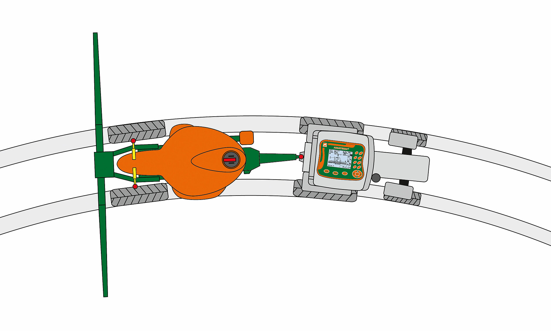
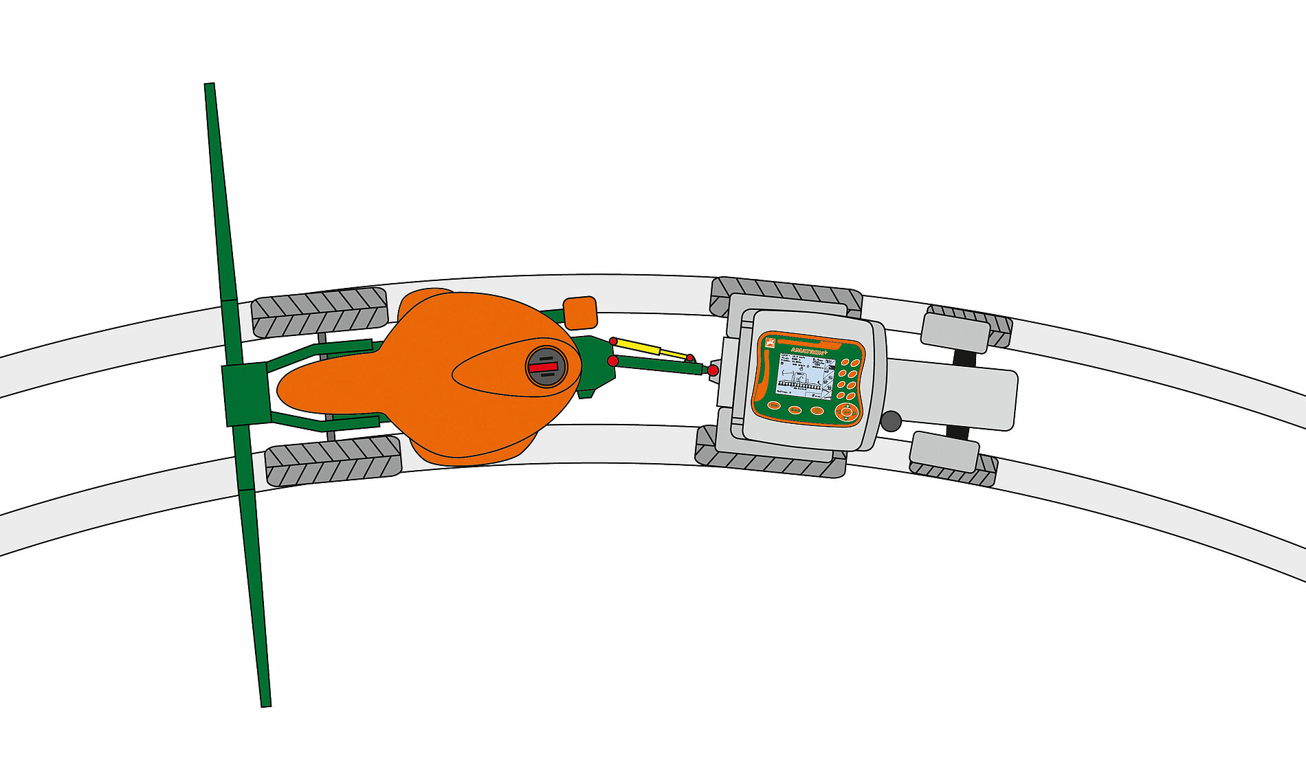
Steered wheels are important on trailed sprayers, particularly in root crops such as potatoes and sugar beets, as the sprayer’s wheels should run along the same tracks as the tractor wheels on cornering in order to minimise damaged caused by driving over plants. On sloping terrain, a steering system can be used to compensate for the offset on a lateral slope. With an Ackerman steering system (Figure 8), the individual wheels are turned as on the tractor’s front axle; in a drawbar steering system, the drawbar turns counter to the sprayer around a central pivot point at the end of the drawbar (Figure 9).
In the mechanical lower link drawbar steering system (self-steering), the sprayer’s drawbar is coupled to the tractor’s lower links. The self-steering system is set by adjusting the drawbar length up to the pivot point at the end of the drawbar (not shown).
The steering types differ primarily in terms of their tracking behaviour and stability (Table 6).
Table 6: Comparison of Ackerman and drawbar steering
| Design | Ackerman steering | Lower link drawbar steering | Hydraulic drawbar steering |
| Tracking behaviour | + | O | - |
| Stability (headland) | + | - | - |
3.6 Fittings
The fitting is the sprayer’s control and operating centre. If manual control devices are used to control the spraying process, the operator must be able to operate a crop protection implement from the driver’s seat. The working pressure, the application quantity (l/ha) (if required), the setting at the fitting and the tank fill level indicator must be clearly legible from the driver’s seat. The pressure setting devices must keep the working pressure constant at a constant pump rotational speed. Seven seconds after a change in the operating status, the measured application quantity may not deviate by more than ± 10 % from the mean application quantity in the new operating status. Changes in operating status can include, e. g. switching off nozzles, changes in speed or section control. Analogue pressure gauges must have a housing with the following minimum diameter:
- 63 mm if they are connected to control devices and lie within the manual reach of the operator or between the coupling points of the three-point linkage and the tractor
- 100 mm in all other cases
The sections can be switched on and off manually, electrically via remote control or automatically. Which system is the most suitable depends on the farm’s structures (Table 7). If a farm has numerous small and irregular fields, automatic section control with a constant pressure fitting offers significant advantages over manual technology. This, in particular, offers scope for significantly relieving the driver and saving PPP’s compared to manually actuated systems.
Table 7: Comparison of various section control systems
| Manual section control | Electric section control | Automatic section control (GPS) | |
| Many small fields | - | O | + |
| Medium fields | - | O | + |
| Large fields | O | O | O |
| Many non-target areas (e. g. wells) | - | O | + |
Evaluation scale: + good/favourable, O average, - poor/unfavourable
3.7 Booms
The working width of the sprayer is usually a full-figure multiple of the working width of the seed drill. The working width must be subdivided into individually controllable sections of a maximum of 4.5 m with boom widths of up to 24 m and a maximum of 6 m with boom widths of over 24 m. The smaller the sections are, the less the overlap when spraying spurs and sloping headlands. This is why smaller sections of 3 m down to individual nozzle actuation for 0.5 m are used in practice. Particularly for use across farms, it is advantageous if the working width can be adapted to different tramline spacings. The height adjustment range of the spraying boom must be at least 1.0 m. It must be possible to adjust the minimum distance between the nozzles and the target area according to the nozzle equipment. On crop spraying implements which are used in crops that grow to a height of more than 1.0 m, the boom’s height adjustment range must be at least 1.2 m. On crop spraying implements with a boom width of up to 21 m, it must be possible to set a minimum height of 0.5 m between the nozzles and the ground. Boom height adjustment must be possible steplessly or in maximum steps of 0.1 m.
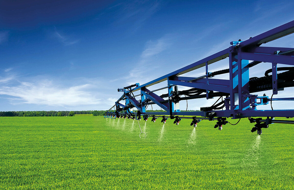
Boom control parallel to the ground is becoming increasingly important in the light of ever-increasing working widths of up to 50 m. Choosing active boom control systems is recommended as of boom widths in excess of 21 m. Two or more ultrasonic sensors are used in these. If two ultrasonic sensors are fitted on the boom extensions, they automatically control the height and lateral inclination of the boom together with two inclination sensors. Precise calibration of the system is the prerequisite for it to function flawlessly. The distance from the target area is then adhered to very accurately in both the longitudinal and the lateral direction. Particularly on changing, slightly sloping terrain and at high driving speeds, automatic boom control is far superior to manual control, even by an experienced driver. Different systems enable adaptation to both the ground and the height of the crop. Which boom control system version is selected ultimately depends on the structure of the land (small – large) or the topography of the terrain (flat – slope).
The design of the boom and the routing of the nozzle lines, when positioned optimally, can also act as nozzle protection to prevent possible nozzle damage.
Active air assistance using an external blower (Figure 10) can prove worthwhile, particularly in windy coastal regions, because these systems significantly extend the spraying period. Extending the spraying period can also prove crucial to success or failure in crops that require intensive spraying, such as potatoes, for instance. This aspect is not to be underestimated, particularly for implements that are used in contracting. However, the power required for the blowers and the increased weight of the boom must not be overlooked.
Boom lighting (Figure 11) is also becoming increasingly important to enable spraying work to be undertaken at the optimum point in time. Central LED headlights (Figure 11) or individual LEDs on the nozzles are suitable for this.
3.8 Nozzles
Nozzles with a spraying angle of 110 to 120 degrees are primarily used in arable farming. The nozzles differ in terms of their design, their size and the material from which they are manufactured. The nozzle material determines the durability of the nozzles. Their resistance to wear increases from plastic to stainless steel to ceramic nozzles. Plastic nozzles are inexpensive, resistant to UAN and adequately wear-resistant for normal conditions. A uniform colour coding (ISO standard 10625) exists for the nozzle size to reduce the risk of using incorrect nozzles. The correct choice of nozzles is of crucial importance to the success of the crop protection measure and can avoid unnecessary environmental pollution. The choice of nozzle form, nozzle size and spray pressure influences the output quantity, the droplet size and therefore also the PPP coating thickness on the plant and the ground. Essentially, large droplets reduce the risk of drift, but also the coating thickness on the parts of the plants. If certain PPP’s that are subject to corresponding buffer zones from bodies of water or terrestrial structures are used (NW or NT requirements), the farmer has the option of using nozzles that are entered in the Julius-Kühn-Institut’s (JKI) directory of drift reducing nozzles. These nozzles are called injector nozzles. A distinction is essentially made between two assemblies in this case: the compact nozzles with a length of approx. 2 to 3 cm (Figure 12, left) and the long nozzles with a length of 4 to 5 cm (Figure 12, right). The spray pressure to be used also differs according to the length. The compact nozzles reveal a good droplet spectrum at 2 to 3 bar and the long nozzles at over 4 bar.
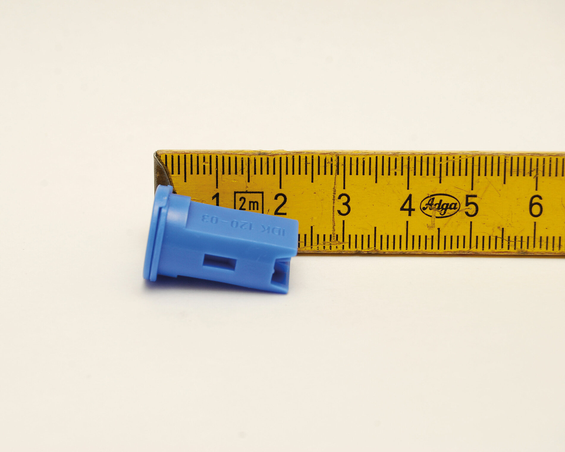
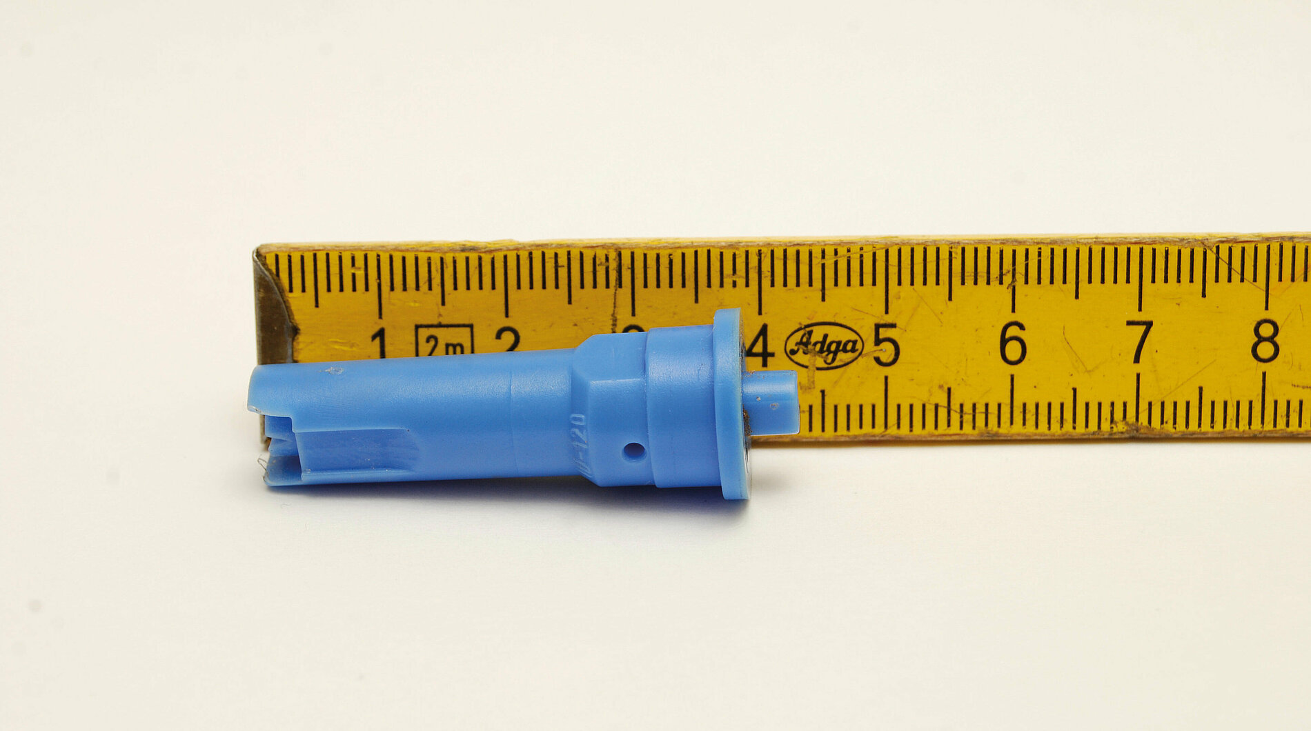
Figure 12: Left: short IDK nozzle from Lechler. Opt. spray pressure 2 bar upwards; right: long ID nozzle from Lechler. Opt. spray pressure 4 bar upwards (source: Kramer)
Table 8: Water application volume ranges (l/ha) of various nozzle sizes at two driving speeds (6 and 8 km/h) in the optimum pressure range of the respective injector nozzle (compact nozzle 1.5 to 3.0 bar and long nozzle 4.0 to 8.0 bar)
| Nozzle size | Compact injector nozzles | Long injector nozzles | ||
| 6 km/h | 8 km/h | 6 km/h | 8 km/h | |
| 1 bar–3 bar | 1 bar–3 bar | 5 bar–8 bar | 5 bar–8 bar | |
| 02 | 92–160 | 69–120 | 207–261 | 155–196 |
| 025 | 115–200 | 87–150 | 258–326 | 194–245 |
| 03 | 139–240 | 104–180 | 310–392 | 232–294 |
| 04 | 185–320 | 139–240 | 413–522 | 310–392 |
| 05 | 231–400 | 173–300 | 516–653 | 387–490 |
In addition to the length, a distinction is also made between flat fan and double flat fan injector nozzles. The double flat fan variants are able to compensate for what is called spray shadow better and are used prior to pre-emergence and in spike treatment. If more than one nozzle set is employed, using a multi-nozzle body on the sprayer is recommended to quickly and conveniently move the desired nozzle into the working position (Figure 13).
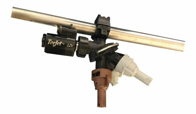
Pulse Width Modulation (PWM) (Figure 14) is relatively new. The PWM valves on the nozzle bodies are used to alternatingly switch the nozzles on the boom on and off at 20 Hz. The duty cycle can be changed as required, which changes the output of each nozzle while maintaining a constant spray pressure and droplet spectrum. It is as if the nozzle calibre were changed during spraying.
A high switching frequency is not necessarily better than a low one. The spraying cone has to form anew with each spraying pulse. The more frequently this occurs, the greater the influence on lateral distribution under certain circumstances. The extent of such an effect depends primarily on which nozzle is used. In principle, a lower frequency in combination with a high driving speed can lead to gaps in longitudinal distribution. This can be reduced or even avoided with alternating switching, i. e. the neighbouring nozzles pulsate alternatingly. The manufacturers of PWM systems specify framework conditions for this under which the systems function reliably. In these systems, the flow and the actual quantity applied are no longer dependent solely on the nozzle calibre, pressure and speed, but also on the pulse width (duty cycle).
PWM is particularly suitable in regions in which high driving speeds are implemented, as a target speed of 15 – 20 km/h cannot be achieved with one nozzle calibre. Further application areas include farms with irregularly shaped fields, fields with numerous obstacles such as masts and ponds, etc. and farms with many fragmented fields. This is where PWM’s curve compensation capability comes into play, because it solves the problem of different application quantities on cornering. On the one hand, individual nozzle control reduces gaps or double application on the headland on fields that are not rectangular; on the other hand, the same quantity is applied with the same droplet spectrum even during the acceleration phase.
So what does PWM offer that other systems cannot do or can only do to a limited extent?
- Individual nozzle control – sensible on the headland on fields that are not rectangular
- Same application quantity and droplet size even at different speeds and when accelerating and braking on the headland (important at high driving speeds)
- Curve compensation in curvaceous tramlines and when bypassing obstacles without under-/over-dosing
- Variation of the output quantity in sub-area-specific cultivation (e. g. growth regulator and liquid fertiliser application)
4 Outlook
In the past, developments in the area of machinery and equipment for plant protection were focused on optimising the implement. For instance, new nozzles reduced drift and optimised boom suspensions reduced over- and under-dosing. In the foreseeable future, the available technologies will be used in farming to limit the area actually treated to the necessary minimum thanks to the widespread use of GPS steering systems in combination with satellite- and/or sensor-supported crop information: Plant Protection Products will only be applied where necessary. This can be optimised from band spraying and nest treatment to individual plant treatment (spot spraying). To do this, the pulse width modulation (PWM) technology, in combination with newly developed nozzles (e. g. SpotFan nozzles), offers the option of applying different quantities with the same droplet spectrum.
5 Literature
[1] DLG-Committee for Crop Protection; von Kröcher, C.; Ahlers, D.: Correct crop protection – things to check before you start DLG Expert Knowledge Series 409 (2015)
[2] DLG-Committee for Crop Protection; von Kröcher, C.; Ahlers, D.: Pflanzenschutz, ohne Wasser zu gefährden (Crop protection without endangering water) DLG Expert Knowledge Series 413 (2016)
[3] Deppe, C.; DLG-Committee for Crop Protection: Lagerung von Pflanzenschutzmitteln auf dem landwirtschaftlichen Betrieb (Storage of crop protection agents on farms) DLG Expert Knowledge Series 452 (2020)
Authors
- Dr. Markus Demmel, Bayerische Landesanstalt für Landwirtschaft, Freising
- Harald Kramer, Landwirtschaftskammer Nordrhein-Westfalen, Münster
- Dr. Norbert Uppenkamp, ehemals Landwirtschaftskammer Nordrhein-Westfalen, Münster
with the involvement of the DLG Committee for Technology in Crop Production
Title image: DLG